William Hackett Yoke Key Eye Point


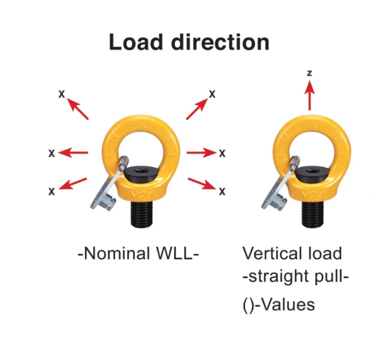
- Rotates through 360° adjustable in the direction of the load.
- Manufactured from alloy steel, quenched and tempered. Captive bolt with high WLL.
- Manufactured and tested in accordance with EN1677-1.
- Load rated parts forged are 100% magnaflux crack detected.
- Individual forged parts and cap screw are traceable to Test Certification.
- Bolts are Metric thread (ASME / ANSI B18.3.1M).
- Proof tested to 2.5 times the WLL.
- Fatigue rated to 1.5 times the WLL.
- Design Factor 4:1.
- All YOKE Lifting points meet or exceed all the requirements of ASME B30.26.
- Quick and simple assembly, just a tapped hole is required.
- 21st century successor to the eye bolt
- Design features make the Key Eye Point resistant to side loading failure and accidental unscrewing
- Pump and valve handling
| Part Code | WLL tonnes | Bolt Size | Box Quantity | Mass (kg) | |
| z | x | ||||
| 8-291K-004 | 1.00 | 0.40 | M10 | 100 | 0.10 |
| 8-291K-007 | 2.00 | 0.75 | M12 | 50 | 0.20 |
| 8-291K-015 | 4.00 | 1.50 | M16 | 50 | 0.30 |
| 8-291K-023 | 6.00 | 2.30 | M20 | 40 | 0.50 |
| 8-291K-032 | 8.00 | 3.20 | M24 | 16 | 0.90 |
| 8-291K-045 | 12.00 | 4.50 | M30 | 12 | 1.70 |
| 8-291K-070 | 16.00 | 7.00 | M36 | 8 | 2.90 |
| 8-291K-090 | 24.00 | 9.00 | M42 | 3 | 4.60 |
| 8-291K-120 | 32.00 | 12.00 | M48 | 3 | 7.00 |
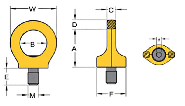
DIMENSIONAL SPECIFICATION
|
WLL tonnes (x - z) |
Thread M (mm) | Thread E (mm) | Pitch DIN13 | A (mm) | B (mm) | C (mm) | D (mm) | F (mm) | S(mm) | W(mm) | Torque in Nm | Mass (kg) |
| 0.40 - 1.00 | M10 | 15 | 1.5 | 36 | 25 | 9 | 9 | 25 | 6 | 44 | 10 | 0.1 |
| 0.75 - 2.00 | M12 | 18 | 1.75 | 45 | 30 | 10 | 11 | 33 | 8 | 52 | 10 | 0.2 |
| 1.50 - 4.00 | M16 | 24 | 2 | 52 | 35 | 14 | 13 | 35 | 10 | 61 | 30 | 0.4 |
| 2.30 - 6.00 | M20 | 30 | 2.5 | 60 | 40 | 16 | 15 | 44 | 12 | 70 | 70 | 0.6 |
| 3.20 - 8.00 | M24 | 36 | 3 | 72 | 48 | 19 | 18 | 53 | 14 | 84 | 150 | 1.1 |
| 4.50 - 12.00 | M30 | 45 | 3.5 | 91 | 61 | 24 | 22 | 62 | 17 | 105 | 350 | 2.1 |
| 7.00 - 16.00 | M36 | 54 | 4 | 110 | 73 | 29 | 27 | 76 | 22 | 126 | 410 | 3.7 |
| 9.00 - 24.00 | M42 | 63 | 4.5 | 128 | 83 | 34 | 32 | 89 | 24 | 147 | 550 | 5.8 |
| 12.00 - 32.00 | M48 | 72 | 5 | 144 | 95 | 38 | 37 | 105 | 27 | 168 | 550 | 8.6 |
LIFTING POINT WORKING LOAD APPLICATION FACTORS
|
|
|
|
|
|
|
|
|
|||
| Number of legs | 1 | 2 | 1 | 2 | 2 | 2 | 3-4 | 3-4 | ||
| Load direction | 0° | 0° | 90° | 90° | 0-45° | 45-60° | unsymm. | 0-45° | 45-60° | unsymm. |
| Thread | WLL tonnes | |||||||||
| M8 | 1 | 2 | 0.3 | 0.6 | 0.42 | 0.3 | 0.3 | 0.63 | 0.45 | 0.3 |
| M10 | 1 | 2 | 0.4 | 0.8 | 0.56 | 0.4 | 0.4 | 0.8 | 0.6 | 0.4 |
| M12 | 2 | 4 | 0.75 | 1.5 | 1 | 0.75 | 0.75 | 1.5 | 1.1 | 0.75 |
| M16 | 4 | 8 | 1.5 | 3 | 2.1 | 1.5 | 1.5 | 3.1 | 2.2 | 1.5 |
| M20 | 6 | 12 | 2.3 | 4.6 | 3.2 | 2.3 | 2.3 | 4.8 | 3.4 | 2.3 |
| M24 | 8 | 16 | 3.2 | 6.4 | 4.5 | 3.2 | 3.2 | 6.7 | 4.8 | 3.2 |
| M30 | 12 | 24 | 4.5 | 9 | 6.3 | 4.5 |
4.5 |
9.4 | 6.7 | 4.5 |
| M36 | 16 | 32 | 7 | 14 | 9.8 | 7 | 7 | 14.7 | 10.5 | 7 |
| M42 | 24 | 48 | 9 | 18 | 12.6 | 9 | 9 | 18.9 | 13.5 | 9 |
| M48 | 32 | 64 | 12 | 24 | 16.8 | 12 | 12 | 25 | 18 | 12 |


Related Products

William Hackett Yoke Lifting Point Metric Thread
Rotates through 360° and pivots 90°. Manufactured from alloy steel, ..
£40.50