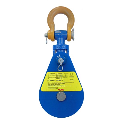
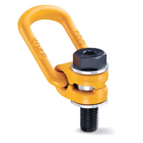
Snatch blocks are typically used for short term and intermittent lifting applications where loads are required to be lifted and moved horizontally. They are easy to transport from location to location and are relatively quick and easy to rig. More permanent arrangements would typically use a crane or a construction block.
Featured
- YOKE snatch blocks are manufactured of the highest quality forged alloy steel.
- Available in sizes 2 tonnes to 20 tonnes.
- Designed with safety factor 4:1.
- Fatigue rated 20000 cycles at 1.5 times the WLL.
- Snatch blocks are supplied with bronze bushings and grease fitting nipples for ease of use and extended shelf life.
- Part number, wire rope size and working load limit are marked on each block.
- Permanent batch codes link to test certificates for easy traceability.
- Meets or exceeds all requirements of ASME B30.26-2010.
- ABS Type Approval Ref. TA1060896-PDA.
| Part Code |
WLL tonnes |
Shaver Diameter |
Wire Rope Size (mm) |
Mass (kg) |
| Inch |
mm |
| 8-541-12 | 12.0 | 6 | 152 | 19-22 | 24.80 |
| 8-541-15 | 15.0 | 8 | 203 | 19-22 | 29.60 |
| 8-541-1510 | 15.0 | 10 | 254 | 19-22 | 42.70 |
**Load On Blocks
Angle Factor Multipliers
The working Load Limit (WLL) for Yoke Group blocks indicates the maximum load that should be exerted on the block and its connecting fitting. this total load value may be different from the weight being lifted or pulled by a hoisting system. it is necessary to determine the total load being imposed on each block in the system properly determine the rated capacity block to be used. A single sheave block used to change the load line direction can be subjected to total loads greatly different from the weight being lifted or pulled. The total load value varies with the angle between the incoming and departing lines to the block. the following chart indicates the factor to be multiplied by the line pull to obtain the total load on the block.
| Angle |
Factor |
Angle |
Factor |
| 0 |
2.00 |
100 |
1.29 |
| 10 |
1.99 |
110 |
1.15 |
| 20 |
1.97 |
120 |
1.00 |
| 30 |
1.93 |
130 |
0.84 |
| 40 |
1.87 |
135 |
0.76 |
| 45 |
1.84 |
140 |
0.68 |
| 50 |
1.81 |
150 |
0.52 |
| 60 |
1.73 |
160 |
0.35 |
| 70 |
1.64 |
170 |
0.17 |
| 80 |
1.53 |
180 |
0.00 |
| 90 |
1.41 |
- |
- |
Sheave size and Wire Rope Strength
| Ratio A |
Strength Efficiency Compared to Catalogue Strength in % |
Ratio A |
Strength Efficiency Compared to Catalogue Strength in %
|
| 40 |
95 |
8 |
83 |
| 30 |
93 |
6 |
79 |
| 20 |
91 |
4 |
75 |
| 15 |
89 |
2 |
65 |
| 10 |
86 |
1 |
50 |
Ratio A = Sheave Diameter ÷ Rope Diameter
Strength Efficiency
Bending wire rope reduces its strength. To account for the effect of bend radius on wire rope strength when selecting a sheave, use the table above
| Ratio B |
Relative Fatigue Bending Life
|
Ratio B |
Relative Fatigue Bending Life |
| 30 |
10.0 |
16 |
2.1 |
| 25 |
6.6 |
14 |
1.5 |
| 20 |
3.8 |
12 |
1.1 |
| 18 |
2.9 |
- |
- |
| Part Code |
WLL tonnes |
Sheave Dia. (mm) |
Wire Rope Size (mm) |
a (mm) |
b (mm) |
e (mm) |
f (mm) |
g (mm) |
k(mm) |
l (mm) |
r (mm) |
Mass (kg) |
| 8-541-12 | 12.0 | 152 | 19-22 | 78 | 80 | 134 | 44 | 167 | 359 | 540 | 496 | 24.8 |
| 8-541-15 | 15.0 | 203 | 19-22 | 78 | 80 | 134 | 44 | 220 | 355 | 589 | 545 | 29.6 |
| 8-541-1510 | 15.0 | 254 | 19-22 | 78 | 80 | 134 | 44 | 280 | 423 | 714 | 670 | 42.7 |
| Part Code |
WLL tonnes |
Sheave Dia. (inches) |
Wire Rope Size (inch) |
a (inch) |
b (inch) |
e (inch) |
f (inch) |
g (inch) |
k(inch) |
l (inch) |
r (inch) |
Mass (lbs.) |
| 8-541-12 | 12 | 6 | 3/4 - 7/8 | 3.07 | 3.15 | 5.28 | 1.73 | 6.57 | 14.13 | 21.26 | 19.63 | 53.6 |
| 8-541-15 | 15 | 8 | 3/4 - 7/8 | 3.07 | 3.15 | 5.28 | 1.73 | 8.66 | 13.99 | 23.19 | 21.46 | 65.1 |
| 8-541-1510 | 15 | 10 | 3/4 - 7/8 | 3.07 | 3.15 | 5.28 | 1.73 | 11.00 | 16.70 | 28.10 | 26.37 | 94.8 |
Load On Blocks
Angle Factor Multipliers
The working Load Limit (WLL) for Yoke Group blocks indicates the maximum load that should be exerted on the block and its connecting fitting. this total load value may be different from the weight being lifted or pulled by a hoisting system. it is necessary to determine the total load being imposed on each block in the system properly determine the rated capacity block to be used. A single sheave block used to change the load line direction can be subjected to total loads greatly different from the weight being lifted or pulled. The total load value varies with the angle between the incoming and departing lines to the block. the following chart indicates the factor to be multiplied by the line pull to obtain the total load on the block.
| Angle |
Factor |
Angle |
Factor |
| 0 |
2.00 |
100 |
1.29 |
| 10 |
1.99 |
110 |
1.15 |
| 20 |
1.97 |
120 |
1.00 |
| 30 |
1.93 |
130 |
0.84 |
| 40 |
1.87 |
135 |
0.76 |
| 45 |
1.84 |
140 |
0.68 |
| 50 |
1.81 |
150 |
0.52 |
| 60 |
1.73 |
160 |
0.35 |
| 70 |
1.64 |
170 |
0.17 |
| 80 |
1.53 |
180 |
0.00 |
| 90 |
1.41 |
- |
- |
Sheave size and Wire Rope Strength
| Ratio A |
Strength Efficiency Compared to Catalogue Strength in % |
Ratio A |
Strength Efficiency Compared to Catalogue Strength in %
|
| 40 |
95 |
8 |
83 |
| 30 |
93 |
6 |
79 |
| 20 |
91 |
4 |
75 |
| 15 |
89 |
2 |
65 |
| 10 |
86 |
1 |
50 |
Ratio A = Sheave Diameter ÷ Rope Diameter
Strength Efficiency
Bending wire rope reduces its strength. To account for the effect of bend radius on wire rope strength when selecting a sheave, use the table above
| Ratio B |
Relative Fatigue Bending Life
|
Ratio B |
Relative Fatigue Bending Life |
| 30 |
10.0 |
16 |
2.1 |
| 25 |
6.6 |
14 |
1.5 |
| 20 |
3.8 |
12 |
1.1 |
| 18 |
2.9 |
- |
- |


